Wednesday, October 19, 2016

Cisco Prime Infrastructure

Cisco Prime Infrastructure (PI) is a browser-based software application that offers the capability to manage wired and wireless network deployments through a single interface. Benefits of Prime Infrastructure include the following:

* Using spatial maps to track devices and show their locations

* Wireless planning tools for AP placements and radio frequency (RF) parameters

* Controller and AP deployment through configuration templates

* Monitoring of controllers, APs, and wireless client devices

* Troubleshooting through alerts, events, wireless interference analysis, and a built-in client troubleshooting tool

* Extensive set of reports that can be automated or run on demand

* Integration with ISE for network access policy management

Note: Prime Infrastructure has undergone an evolution over time. You might come across the names of its earlier generations as you read and study: Cisco Wireless Control System (WCS) and Cisco Prime Network Control System (NCS). Keep in mind that the CCNA WIFUND 200-355 exam is limited to Prime Infrastructure version 2.2

The home page is organized into several sections or areas. The Task Area is a row of drop-down menus organized into lifecycle tasks.


Lifecycle Task        Description

Dashboard               Display concise dashboards of network activity or information

Monitor                   Display common day-to-day monitoring, troubleshooting, maintenance, and
                                operations dashboards

Configuration         Manage configuration templates and profiles that can be deployed onto the
                                network infrastructure

Inventory                Manage the inventory of network devices, their software, and configuration
                                archives

Maps                       Manage and view network topology maps and spatial maps of wireless
                                information

Services                   Access mobility services and Application Visibility and Control (AVC)
                                 services

Reports                    Create, view, and run a robust set of reports

Administration        Manage the Prime Infrastructure server


I've used the Cisco Prime Infrastructure server (version 2.2) in dCloud and re-configured my wireless lab.


SW1(config)#vlan 10
SW1(config-vlan)#name WIRED_DATA
SW1(config-vlan)#vlan 11
SW1(config-vlan)#name WIRELESS_DATA
SW1(config)#interface f0/24   // TRUNK TO ROUTER
SW1(config-if)#switchport trunk encapsulation dot1q
SW1(config-if)#switchport mode trunk
SW1(config)#interface vlan 10
*Mar  1 01:22:22.282: %LINEPROTO-5-UPDOWN: Line protocol on Interface Vlan10, changed state to up
SW1(config-if)#ip address 10.72.235.194 255.255.255.240
SW1(config-if)#ip default-gateway 10.72.235.193
SW1(config)#interface f0/23    // TO CLIENT PC
SW1(config-if)#switchport access vlan 10
SW1(config-if)#shut
SW1(config-if)#no shut
SW1(config)#interface f0/1   // TRUNK TO WLC
SW1(config-if)#switchport trunk encapsulation dot1q
SW1(config-if)#switchport trunk native vlan 10
SW1(config-if)#switchport mode trunk
SW1(config)#int f0/14   // TO AP
SW1(config-if)#switchport access vlan 10
SW1(config-if)#shut
SW1(config-if)#no shut


(Cisco Controller) >show interface summary


 Number of Interfaces.......................... 2

Interface Name                   Port Vlan Id  IP Address      Type    Ap Mgr Gu
est
-------------------------------- ---- -------- --------------- ------- ------ --
---
management                       1    untagged 192.168.1.4     Static  Yes    No

virtual                          N/A  N/A      10.1.1.1        Static  No     No


(Cisco Controller) >config interface address ?

dynamic-interface Enter interface name.
management     Configures the management interface.
virtual        Configures the virtual gateway interface.

(Cisco Controller) >config interface address management ?

<IP address>   Enter the interface's IP Address.

(Cisco Controller) >config interface address management 10.72.235.195 ?

<netmask>      Enter the interface's netmask.

(Cisco Controller) >config interface address management 10.72.235.195 255.255.255.240 ?

<gateway>      Enter the interface's gateway address.

(Cisco Controller) >config interface address management 10.72.235.195 255.255.255.240 10.72.235.193

Request failed - Active WLAN using interface. Disable WLAN first.

(Cisco Controller) >config wlan ?

7920-support   Configures support for phones.
aaa-override   Configures user policy override via AAA on a WLAN.
acl            Specify a per-WLAN ACL
apgroup        Manage AP Groups VLAN feature.
assisted-roaming Configures Assisted Roaming on a WLAN.
avc            Configure AVC.
band-select    Allow|Disallow Band Select on a WLAN.
broadcast-ssid Configures SSID Broadcast on a WLAN.
bssmaxidle     Configures BSS Max Idle Processing on a WLAN.
call-snoop     Configures Call Snooping.
ccx            Configure Cisco Client Extension options.
channel-scan   Configures off channel scanning deferral parameters.
chd            Enable/Disable CHD per WLAN
create         Creates a WLAN.
custom-web     Configures the Web Authentication Page per Profile.
delete         Deletes a WLAN.
dhcp_server    Configures the WLAN's DHCP Server.
diag-channel   Configures Diagnostics Channel Capability on a WLAN.
disable        Disables a WLAN.
dms            Configures DMS Processing on a WLAN.
dtim           Configures the DTIM Period for a WLAN

--More-- or (q)uit

Incorrect usage.  Use the '?' or <TAB> key to list commands.

(Cisco Controller) >config wlan disable ?

<WLAN id>      Enter WLAN Identifier between 1 and 16.
all            Configure all WLANs.
foreignAp      Third Party Access Points.

(Cisco Controller) >config wlan disable all
(Cisco Controller) >config interface address management 10.72.235.195 255.255.255.240 10.72.235.193
(Cisco Controller) >config wlan enable all
(Cisco Controller) >show ap summary

Number of APs.................................... 1

Global AP User Name.............................. Not Configured
Global AP Dot1x User Name........................ Not Configured

AP Name             Slots  AP Model              Ethernet MAC       Location          Country 

IP Address       Clients
------------------  -----  --------------------  -----------------  ----------------  ------- 

---------------  -------
APf872.eaa6.e203     2     AIR-CAP2602I-S-K9     f8:72:ea:a6:e2:03  default location  SG      

10.72.235.197    0


H:\>ipconfig

Windows IP Configuration


Wireless LAN adapter Wireless Network Connection 3:

   Media State . . . . . . . . . . . : Media disconnected
   Connection-specific DNS Suffix  . :

Wireless LAN adapter Wireless Network Connection 2:

   Media State . . . . . . . . . . . : Media disconnected
   Connection-specific DNS Suffix  . :

Wireless LAN adapter Wireless Network Connection:

   Media State . . . . . . . . . . . : Media disconnected
   Connection-specific DNS Suffix  . : lagura.com

Ethernet adapter Local Area Connection:

   Connection-specific DNS Suffix  . : dcloud.cisco.com
   IPv4 Address. . . . . . . . . . . : 10.72.235.196
   Subnet Mask . . . . . . . . . . . : 255.255.255.240
   Default Gateway . . . . . . . . . : 10.72.235.193


H:\>ping 10.72.235.193    // PING TO ROUTER VLAN 10 GATEWAY

Pinging 10.72.235.193 with 32 bytes of data:
Reply from 10.72.235.193: bytes=32 time=1ms TTL=255

Ping statistics for 10.72.235.193:
    Packets: Sent = 4, Received = 4, Lost = 0 (0% loss),
Approximate round trip times in milli-seconds:
    Minimum = 1ms, Maximum = 1ms, Average = 1ms


H:\>ping 10.72.235.194   // PING TO SWITCH

Pinging 10.72.235.194 with 32 bytes of data:
Reply from 10.72.235.194: bytes=32 time=2ms TTL=255
Reply from 10.72.235.194: bytes=32 time=1ms TTL=255

Ping statistics for 10.72.235.194:
    Packets: Sent = 4, Received = 4, Lost = 0 (0% loss),
Approximate round trip times in milli-seconds:
    Minimum = 1ms, Maximum = 2ms, Average = 1ms

H:\>ping 10.72.235.195   // PING TO WLC

Pinging 10.72.235.195 with 32 bytes of data:
Reply from 10.72.235.195: bytes=32 time=1ms TTL=128

Ping statistics for 10.72.235.195:
    Packets: Sent = 4, Received = 4, Lost = 0 (0% loss),
Approximate round trip times in milli-seconds:
    Minimum = 1ms, Maximum = 1ms, Average = 1ms

H:\>tracert 8.8.8.8

Tracing route to google-public-dns-a.google.com [8.8.8.8]
over a maximum of 30 hops:

  1     1 ms     1 ms     1 ms  10.72.235.193
  2    16 ms    12 ms     8 ms  1.104.165.222.starhub.net.sg [222.165.104.1]
  3    11 ms     8 ms     8 ms  1.104.165.222.starhub.net.sg [222.165.104.1]
  4     7 ms     6 ms     7 ms  172.24.43.65
  5    12 ms    11 ms    15 ms  172.20.7.162
  6     9 ms    12 ms    11 ms  203.117.37.205
  7    11 ms    11 ms    11 ms  203.117.36.37
  8    41 ms     9 ms    12 ms  203.117.34.38
  9     8 ms    11 ms    11 ms  72.14.196.189
 10    13 ms    11 ms    10 ms  108.170.240.97
 11    12 ms    11 ms    11 ms  209.85.240.199
 12     8 ms    11 ms    10 ms  google-public-dns-a.google.com [8.8.8.8]

Trace complete.


To add a WLC on PI, you first configure SNMP on the WLC by going to Management > SNMP > Communities > type the Prime Infrastructure server IP address, select Enable and click Apply.


Next, add the WLC on PI by going to Configuration> Network Devices > Add Device.


Type the WLC management IP address, SNMP community string and click Add. You’ll notice that it will synchronize with the WLC and status will change to Completed.


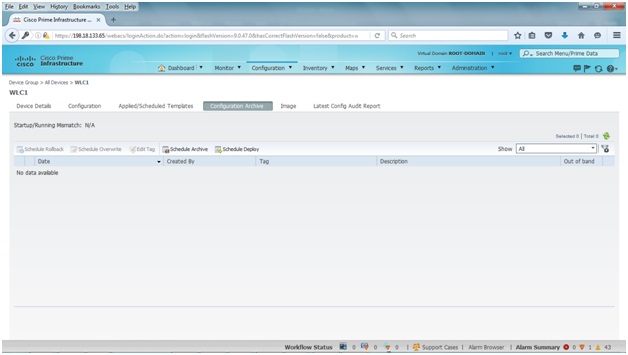
You'll be able to see all the WLC details by clicking on the tabs such as Device Details, Configuration, etc.


You can also view the same tabs under Monitor.


You can view various device health graphs and statistics under Dashboard.


You can also monitor and view the details of the associated wireless clients by going to Monitor > Clients and Users. Click the radio button beside the MAC address to view the client’s full details.


Friday, October 14, 2016

Configuring DHCP on a Cisco WLC

I visited my sister a month ago and spent a day in Dubai before going together for our trip to New York. I had a chance to put on an Arabian traditional wear and be a Sheikh for a day. There's a lot of Filipino expats in Dubai which made it easy for us to shop and dine almost everywhere.


Cisco wireless controllers support the following interface types:

* Management interface - Used for normal management traffic, such as RADIUS user authentication, WLC-to-WLC communication, web-based and SSH sessions, SNMP, Network Time Protocol (NTP), syslog, and so on.

* AP-manager interface - A dynamic interface used to terminate CAPWAP tunnels between the controller and its APs. If no AP-manager interface is created, the function is performed by the manager interface instead.

* Virtual interface - IP address facing wireless clients when the controller is relaying client DHCP requests, performing client web authentication, and supporting client mobility.

* Service port interface (available on WLC 5508 and higher) - Bound to the service port and used for out-of-band management.

* Dynamic interface - Used to connect a VLAN to a WLAN.

The management interface faces the switched network, where management users and APs are located. Management traffic will usually consists of protocols like HTTPS, SSH, SNMP, NTP, TFTP, and so on. In addition, management interface traffic consists of CAPWAP packets that carry control and data tunnels to and from the APs.

The virtual interface is used only for certain client-facing operations. For example, when a wireless client issues a DHCP request to obtain an IP address, the controller can relay the request on to a normal DHCP server. From the client's perspective, the DHCP server appears to be the controller's virtual interface address. Clients may see the virtual interface's address, but that address is never used when the controller communicates with other devices on the switched network.

Because the virtual interface is used only for some client management functions, you should configure it with a unique, nonroutable address. For example, you might use 10.1.1.1 because it is within a private address space defined in RFC 1918.

Tip: Traditionally, many people have assigned IP address 1.1.1.1 to the virtual interface. Although it is a unique address, it is routable and already in use elsewhere on the Internet. A better practice is to use an IP address from the RFC 1918 private address space that is unused or reserved, such as 192.168.1.1. You could also use a reserved address from RFC 5737 (192.0.2.0/24) that is set aside for documentation purposes and is never used.

The virtual address is also used to support client mobility. For that reason, every controller that exists in the same mobility group should be configured with a virtual address that is identical to the others. By using one common virtual address, all the controllers will appear to operate as a cluster as clients roam from controller to controller.

Dynamic interfaces map WLANs to VLANs, making the logical connections between wireless and wired networks. You will configure one dynamic interface for each wireless LAN that is offered by the controller's AP, and then map the interface to the WLAN. Each dynamic interface must also be configured with its own IP address and can act as a DHCP relay for wireless clients. To filter traffic passing through a dynamic interface, you can configure an optional access list.


In my wireless lab, I've disabled DHCP on R1 and moved it to WLC1.

R1#configure terminal
Enter configuration commands, one per line.  End with CNTL/Z.
R1(config)#no ip dhcp excluded-address 10.72.235.193 10.72.235.196
R1(config)#no ip dhcp pool wired-data


Below are the steps in order to create a DHCP Scope in a WLC. You go to Controller > Internal DHCP Server > DHCP Scope > click New.


Type the Scope Name and click Apply.


Click on the newly created Scope Name.


Type DHCP Network Info, choose Enabled under Status and click Apply.


Go to Controller > Interfaces > click Interface Name > type the DHCP IP Address under Primary DHCP Server. You type the WLC management IP address for the WLANs/VLANs other than Management.


Go to WLANs > click WLAN ID > Advanced > tick Override under DHCP Server and type DHCP Server IP address which is the WLC Management IP address > click Apply > Save Configuration.


To verify DHCP leases go to Controller > Internal DHCP Server > DHCP Allocated Leases.


(Cisco Controller) >debug dhcp packet enable     // THIS IS A HANDY WLC DEBUG COMMAND FOR TROUBLESHOOTING DHCP ERRORS; TO STOP ISSUE A debug dhcp packet disable
(Cisco Controller) >*DHCP Socket Task: Oct 08 13:59:08.918: d0:25:98:90:1c:d9 DHCP received op BOOTREQUEST (1) (len 308,vlan 0, port 1, encap 0xec03)
*DHCP Socket Task: Oct 08 13:59:08.918: d0:25:98:90:1c:d9 DHCP (encap type 0xec03) mstype 0ff:ff:ff:ff:ff:ff
*DHCP Socket Task: Oct 08 13:59:08.918: d0:25:98:90:1c:d9 DHCP selecting relay 1 - control block settings:
                        dhcpServer: 0.0.0.0, dhcpNetmask: 0.0.0.0,
                        dhcpGateway: 0.0.0.0, dhcpRelay: 0.0.0.0  VLAN: 0
*DHCP Socket Task: Oct 08 13:59:08.918: d0:25:98:90:1c:d9 DHCP selected relay 1 - 10.72.235.195 (local address 10.72.235.195, gateway 10.72.235.195, VLAN 0, port 1)
*DHCP Socket Task: Oct 08 13:59:08.918: d0:25:98:90:1c:d9 DHCP selecting relay 2 - control block settings:
                        dhcpServer: 0.0.0.0, dhcpNetmask: 0.0.0.0,
                        dhcpGateway: 0.0.0.0, dhcpRelay: 10.72.235.195  VLAN: 0
*DHCP Socket Task: Oct 08 13:59:08.918: d0:25:98:90:1c:d9 DHCP selected relay 2 - NONE (server address 0.0.0.0,local address 10.72.235.195, gateway 10.72.235.193, VLAN 0, port 1)
*DHCP Socket Task: Oct 08 13:59:08.918: d0:25:98:90:1c:d9 DHCP selecting relay 1 - control block settings:
                        dhcpServer: 0.0.0.0, dhcpNetmask: 0.0.0.0,
                        dhcpGateway: 0.0.0.0, dhcpRelay: 10.72.235.195  VLAN: 0
*DHCP Socket Task: Oct 08 13:59:08.918: d0:25:98:90:1c:d9 DHCP selected relay 1 - 10.72.235.195 (local address 10.72.235.195, gateway 10.72.235.195, VLAN 0, port 1)
*DHCP Socket Task: Oct 08 13:59:08.918: d0:25:98:90:1c:d9 DHCP transmitting DHCP DISCOVER (1)
*DHCP Socket Task: Oct 08 13:59:08.918: d0:25:98:90:1c:d9 DHCP   op: BOOTREQUEST, htype: Ethernet, hlen: 6, hops: 1
*DHCP Socket Task: Oct 08 13:59:08.918: d0:25:98:90:1c:d9 DHCP   xid: 0x2fc94a87 (801720967), secs: 0, flags: 0
*DHCP Socket Task: Oct 08 13:59:08.918: d0:25:98:90:1c:d9 DHCP   chaddr: d0:25:98:90:1c:d9
*DHCP Socket Task: Oct 08 13:59:08.918: d0:25:98:90:1c:d9 DHCP   ciaddr: 0.0.0.0,  yiaddr: 0.0.0.0
*DHCP Socket Task: Oct 08 13:59:08.918: d0:25:98:90:1c:d9 DHCP   siaddr: 0.0.0.0,  giaddr: 10.72.235.195
*DHCP Socket Task: Oct 08 13:59:08.918: d0:25:98:90:1c:d9 DHCP selecting relay 2 - control block settings:
                        dhcpServer: 0.0.0.0, dhcpNetmask: 0.0.0.0,
                        dhcpGateway: 0.0.0.0, dhcpRelay: 10.72.235.195  VLAN: 0
*DHCP Socket Task: Oct 08 13:59:08.918: d0:25:98:90:1c:d9 DHCP selected relay 2 - NONE (server address 0.0.0.0,local address 0.0.0.0, gateway 10.72.235.193, VLAN 0, port 1)
*DHCP Proxy Task: Oct 08 13:59:08.920: d0:25:98:90:1c:d9 DHCP received op BOOTREPLY (2) (len 572,vlan 0, port 0, encap 0x0)
*DHCP Proxy Task: Oct 08 13:59:08.920: d0:25:98:90:1c:d9 DHCP setting server from OFFER (server 10.72.235.195, yiaddr 10.72.235.198)
*DHCP Proxy Task: Oct 08 13:59:08.920: d0:25:98:90:1c:d9 DHCP sending REPLY to STA (len 414, port 1, vlan 0)
*DHCP Proxy Task: Oct 08 13:59:08.920: d0:25:98:90:1c:d9 DHCP transmitting DHCP OFFER (2)
*DHCP Proxy Task: Oct 08 13:59:08.920: d0:25:98:90:1c:d9 DHCP   op: BOOTREPLY, htype: Ethernet, hlen: 6, hops: 0
*DHCP Proxy Task: Oct 08 13:59:08.920: d0:25:98:90:1c:d9 DHCP   xid: 0x2fc94a87 (801720967), secs: 0, flags: 0
*DHCP Proxy Task: Oct 08 13:59:08.920: d0:25:98:90:1c:d9 DHCP   chaddr: d0:25:98:90:1c:d9
*DHCP Proxy Task: Oct 08 13:59:08.920: d0:25:98:90:1c:d9 DHCP   ciaddr: 0.0.0.0,  yiaddr: 10.72.235.198
*DHCP Proxy Task: Oct 08 13:59:08.920: d0:25:98:90:1c:d9 DHCP   siaddr: 0.0.0.0,  giaddr: 0.0.0.0
*DHCP Proxy Task: Oct 08 13:59:08.920: d0:25:98:90:1c:d9 DHCP   server id: 10.1.1.1  rcvd server id: 10.72.235.195
*DHCP Socket Task: Oct 08 13:59:09.932: d0:25:98:90:1c:d9 DHCP received op BOOTREQUEST (1) (len 308,vlan 0, port 1, encap 0xec03)
*DHCP Socket Task: Oct 08 13:59:09.932: d0:25:98:90:1c:d9 DHCP (encap type 0xec03) mstype 0ff:ff:ff:ff:ff:ff
*DHCP Socket Task: Oct 08 13:59:09.933: d0:25:98:90:1c:d9 DHCP selecting relay 1 - control block settings:
                        dhcpServer: 10.72.235.195, dhcpNetmask: 0.0.0.0,
                        dhcpGateway: 0.0.0.0, dhcpRelay: 10.72.235.195  VLAN: 0
*DHCP Socket Task: Oct 08 13:59:09.933: d0:25:98:90:1c:d9 DHCP mscbVapLocalAddr=10.72.235.195 mscbVapLocalNetMask= 255.255.255.240 mscbdhcpRelay=10.72.235.195
*DHCP Socket Task: Oct 08 13:59:09.933: d0:25:98:90:1c:d9 DHCP selected relay 1 - 10.72.235.195 (local address 10.72.235.195, gateway 10.72.235.195, VLAN 0, port 1)
*DHCP Socket Task: Oct 08 13:59:09.933: d0:25:98:90:1c:d9 DHCP transmitting DHCP REQUEST (3)
*DHCP Socket Task: Oct 08 13:59:09.933: d0:25:98:90:1c:d9 DHCP   op: BOOTREQUEST, htype: Ethernet, hlen: 6, hops: 1
*DHCP Socket Task: Oct 08 13:59:09.933: d0:25:98:90:1c:d9 DHCP   xid: 0x2fc94a87 (801720967), secs: 1, flags: 0
*DHCP Socket Task: Oct 08 13:59:09.933: d0:25:98:90:1c:d9 DHCP   chaddr: d0:25:98:90:1c:d9
*DHCP Socket Task: Oct 08 13:59:09.933: d0:25:98:90:1c:d9 DHCP   ciaddr: 0.0.0.0,  yiaddr: 0.0.0.0
*DHCP Socket Task: Oct 08 13:59:09.933: d0:25:98:90:1c:d9 DHCP   siaddr: 0.0.0.0,  giaddr: 10.72.235.195
*DHCP Socket Task: Oct 08 13:59:09.933: d0:25:98:90:1c:d9 DHCP   requested ip: 10.72.235.198
*DHCP Socket Task: Oct 08 13:59:09.933: d0:25:98:90:1c:d9 DHCP   server id: 10.72.235.195  rcvd server id: 10.1.1.1
*DHCP Socket Task: Oct 08 13:59:09.933: d0:25:98:90:1c:d9 DHCP selecting relay 2 - control block settings:
                        dhcpServer: 10.72.235.195, dhcpNetmask: 0.0.0.0,
                        dhcpGateway: 0.0.0.0, dhcpRelay: 10.72.235.195  VLAN: 0
*DHCP Socket Task: Oct 08 13:59:09.933: d0:25:98:90:1c:d9 DHCP selected relay 2 - NONE
*DHCP Proxy Task: Oct 08 13:59:09.934: d0:25:98:90:1c:d9 DHCP received op BOOTREPLY (2) (len 572,vlan 0, port 0, encap 0x0)
*DHCP Proxy Task: Oct 08 13:59:09.934: d0:25:98:90:1c:d9 DHCP setting server from ACK (mscb=0x3ef11e00 ip=0xa48ebc6)(server 10.72.235.195, yiaddr 10.72.235.198)
*DHCP Proxy Task: Oct 08 13:59:09.935: d0:25:98:90:1c:d9 Assigning Address 10.72.235.198 to mobile      // THIS IS MY iPHONE GOING THROUGH THE DHCP D.O.R.A PROCESS
*DHCP Proxy Task: Oct 08 13:59:09.935: d0:25:98:90:1c:d9 DHCP success event for client. Clearing dhcp failure count for interface management.
*DHCP Proxy Task: Oct 08 13:59:09.935: d0:25:98:90:1c:d9 DHCP sending REPLY to STA (len 414, port 1, vlan 0)
*DHCP Proxy Task: Oct 08 13:59:09.935: d0:25:98:90:1c:d9 DHCP transmitting DHCP ACK (5)
*DHCP Proxy Task: Oct 08 13:59:09.935: d0:25:98:90:1c:d9 DHCP   op: BOOTREPLY, htype: Ethernet, hlen: 6, hops: 0
*DHCP Proxy Task: Oct 08 13:59:09.935: d0:25:98:90:1c:d9 DHCP   xid: 0x2fc94a87 (801720967), secs: 0, flags: 0
*DHCP Proxy Task: Oct 08 13:59:09.935: d0:25:98:90:1c:d9 DHCP   chaddr: d0:25:98:90:1c:d9
*DHCP Proxy Task: Oct 08 13:59:09.935: d0:25:98:90:1c:d9 DHCP   ciaddr: 0.0.0.0,  yiaddr: 10.72.235.198
*DHCP Proxy Task: Oct 08 13:59:09.935: d0:25:98:90:1c:d9 DHCP   siaddr: 0.0.0.0,  giaddr: 0.0.0.0
*DHCP Proxy Task: Oct 08 13:59:09.935: d0:25:98:90:1c:d9 DHCP   server id: 10.1.1.1  rcvd server id: 10.72.235.195
*DHCP Socket Task: Oct 08 13:59:18.224: 20:a2:e4:10:e7:1f DHCP received op BOOTREQUEST (1) (len 308,vlan 0, port 1, encap 0xec03)
*DHCP Socket Task: Oct 08 13:59:18.224: 20:a2:e4:10:e7:1f DHCP (encap type 0xec03) mstype 0ff:ff:ff:ff:ff:ff
*DHCP Socket Task: Oct 08 13:59:18.224: 20:a2:e4:10:e7:1f DHCP selecting relay 1 - control block settings:
                        dhcpServer: 0.0.0.0, dhcpNetmask: 0.0.0.0,
                        dhcpGateway: 0.0.0.0, dhcpRelay: 0.0.0.0  VLAN: 0
*DHCP Socket Task: Oct 08 13:59:18.224: 20:a2:e4:10:e7:1f DHCP selected relay 1 - 10.72.235.195 (local address 10.72.235.195, gateway 10.72.235.195, VLAN 0, port 1)
*DHCP Socket Task: Oct 08 13:59:18.224: 20:a2:e4:10:e7:1f DHCP transmitting DHCP REQUEST (3)
*DHCP Socket Task: Oct 08 13:59:18.224: 20:a2:e4:10:e7:1f DHCP   op: BOOTREQUEST, htype: Ethernet, hlen: 6, hops: 1
*DHCP Socket Task: Oct 08 13:59:18.224: 20:a2:e4:10:e7:1f DHCP   xid: 0x1bb0cf0b (464572171), secs: 0, flags: 0
*DHCP Socket Task: Oct 08 13:59:18.224: 20:a2:e4:10:e7:1f DHCP   chaddr: 20:a2:e4:10:e7:1f
*DHCP Socket Task: Oct 08 13:59:18.224: 20:a2:e4:10:e7:1f DHCP   ciaddr: 0.0.0.0,  yiaddr: 0.0.0.0
*DHCP Socket Task: Oct 08 13:59:18.224: 20:a2:e4:10:e7:1f DHCP   siaddr: 0.0.0.0,  giaddr: 10.72.235.195
*DHCP Socket Task: Oct 08 13:59:18.224: 20:a2:e4:10:e7:1f DHCP   requested ip: 10.72.235.197
*DHCP Socket Task: Oct 08 13:59:18.224: 20:a2:e4:10:e7:1f DHCP selecting relay 2 - control block settings:
                        dhcpServer: 0.0.0.0, dhcpNetmask: 0.0.0.0,
                        dhcpGateway: 0.0.0.0, dhcpRelay: 10.72.235.195  VLAN: 0
*DHCP Socket Task: Oct 08 13:59:18.224: 20:a2:e4:10:e7:1f DHCP selected relay 2 - NONE (server address 0.0.0.0,local address 0.0.0.0, gateway 10.72.235.193, VLAN 0, port 1)
*DHCP Proxy Task: Oct 08 13:59:18.226: 20:a2:e4:10:e7:1f DHCP received op BOOTREPLY (2) (len 572,vlan 0, port 0, encap 0x0)
*DHCP Proxy Task: Oct 08 13:59:18.226: 20:a2:e4:10:e7:1f DHCP setting server from ACK (mscb=0x3ef135d0 ip=0xa48ebc5)(server 10.72.235.195, yiaddr 10.72.235.197)
*DHCP Proxy Task: Oct 08 13:59:18.227: 20:a2:e4:10:e7:1f DHCP setting server from ACK (server 10.72.235.195, yiaddr 10.72.235.197)
*DHCP Proxy Task: Oct 08 13:59:18.227: 20:a2:e4:10:e7:1f Assigning Address 10.72.235.197 to mobile
*DHCP Proxy Task: Oct 08 13:59:18.227: 20:a2:e4:10:e7:1f DHCP success event for client. Clearing dhcp failure count for interface management.
*DHCP Proxy Task: Oct 08 13:59:18.227: 20:a2:e4:10:e7:1f DHCP sending REPLY to STA (len 414, port 1, vlan 0)
*DHCP Proxy Task: Oct 08 13:59:18.227: 20:a2:e4:10:e7:1f DHCP transmitting DHCP ACK (5)
*DHCP Proxy Task: Oct 08 13:59:18.227: 20:a2:e4:10:e7:1f DHCP   op: BOOTREPLY, htype: Ethernet, hlen: 6, hops: 0
*DHCP Proxy Task: Oct 08 13:59:18.227: 20:a2:e4:10:e7:1f DHCP   xid: 0x1bb0cf0b (464572171), secs: 0, flags: 0
*DHCP Proxy Task: Oct 08 13:59:18.227: 20:a2:e4:10:e7:1f DHCP   chaddr: 20:a2:e4:10:e7:1f
*DHCP Proxy Task: Oct 08 13:59:18.227: 20:a2:e4:10:e7:1f DHCP   ciaddr: 0.0.0.0,  yiaddr: 10.72.235.197
*DHCP Proxy Task: Oct 08 13:59:18.227: 20:a2:e4:10:e7:1f DHCP   siaddr: 0.0.0.0,  giaddr: 0.0.0.0
*DHCP Proxy Task: Oct 08 13:59:18.227: 20:a2:e4:10:e7:1f DHCP   server id: 10.1.1.1  rcvd server id: 10.72.235.195

Friday, October 7, 2016

Understanding Types of Wireless Interference

I finally got my CCNA Wireless cert from mail today and below is how it looks like. To further advance my knowledge in the wireless domain, I've been studying for CWNA and hope to get certified before 2016 ends. I'm using CWNA-106 Official Study Guide by Coleman and Westcott and Jerome Henry's CCNA Wireless Live Lessons video course for my studies. I highly recommend Jerome Henry's videos since he tackles a wide range of wireless topics including RF communications, site survey, wireless architecture and implementation, etc. This would be my 5th IT cert if I pass it this year. I might also get CWSP next year and hopefully to get back on my security track and take Palo Alto ACE since it's free.


If two APs are configured to use the same channel and are in close proximity to each other, co-channel interference results. If the APs are set to use adjacent or overlapping channels, adjacent channel interference occurs. While those types of interference can certainly be destructive, they involve devices that are based on the 802.11 standard. For example, each access point (AP) transmits on a specific channel (possibly the wrong one!), uses a standardized channel width, and always transmits frames in the 802.11 format. As well, each AP should also follow the 802.11 rules for clear channel assessment (CCA) to maintain some etiquette to share the airtime.

Rogue APs can be a significant and pesky source of interference because they usually belong to someone else. In other words, someone outside your organization is free to bring up their own APs on channels of their choosing. As long as signals from their APs can be received within your own AP cells, you might have to deal with the interference. To mitigate the problem, you must do one of the following:

* Find the rogue AP and its owner, and then convince the owner to remove the AP or change its channel.

* Move your own AP to a different channel, which may cause other nearby APs to be moved too. When 802.11 devices interfere with each other, the result is usually poor performance due to frame re-transmissions, errors, and the lack of available airtime. In other words, the 802.11 data can still be detected but not always correctly received. In contrast, non-802.11 devices do not have to obey any of the familiar 802.11 rules. When a non-802.11 device transmits, the result is completely incompatible with 802.11. APs and 802.11 clients will view the signal as unintelligible and regard it as noise.

The following sections provide an overview of some common non-802.11 devices that can interfere with a WLAN. As you work through this chapter, keep the following two terms in mind:

* Interference - 802.11 signals that come from sources other than expected APs

* Noise - Signals or radio frequency (RF) energy that reduces the signal-to-noise ratio (SNR) and disrupts transmission or reception of an 802.11 signal.


Bluetooth

Bluetooth is a technology used to form a personal-area network (PAN), in an effort to unify telephony and computing devices. Today, Bluetooth can be found integrated into cell phones, tablets, laptops, desktops, printers, headsets, cameras, and video game consoles Bluetooth has low power consumption, making it a good choice for mobile, battery-powered devices. Bluetooth began as Versions 1.0 and 1.0b, developed by the Bluetooth Special Interest Group (SIG).

For a time, several Bluetooth versions were incorporated into the IEEE 802.15.1 standard, but that standard is no longer maintained. The Bluetooth SIG continued to develop its own standard, currently published as core Version 4.

Bluetooth devices are grouped into three classes according to their radiated power. Classes 1 and 2 are the most common and use a maximum transmit power level of 1 mW and 2.5 mW, respectively. Because Bluetooth operates as a PAN, class 1 and 2 devices use a relatively low transmit power level and have a range of only 35 feet. Less common, "industrial" Bluetooth class 3 devices can operate up to 100 mW.

Bluetooth Low Energy (BLE) was designed for the Internet of Things (IoT), allowing small devices such as smartphones and tablets to transmit up to 20 dBm over a range of 100 meters. Apple has implemented BLE as its iBeacon technology, commonly used to interface with shoppers' mobile devices in retail stores. iBeacon can gather location information from devices, detect shoppers' proximity to items, push notifications such as advertisements and coupons to devices, and collect mobile payments.

Up to eight devices can be paired or linked into a PAN, with one device takin a master role and the others operating as slaves. 


ZigBee

ZigBee is wireless LAN technology that is based on relatively low power consumption and low data rates (20 to 250 Kbps). As a result, it offers reliable communication. ZigBee is commonly used for energy management and home and building automatication applications.

ZigBee is defined in the IEEE 802.15.4 standard. It allocates the 2.4-GHz ISM band into 16 channels of 5 MHz each. Even through ZigBee uses the same band as 802.11 devices, it has a low duty cycle and does not utilize a channel much of the time. As well, ZigBee devices normally use a low transmit power level, which minimizes interference, but can ramp up to a maximum of 60 mW when necessary.


Cordless Phones

Cordless pones use several wireless technologies to connect remote handsets to a central base station. Phones that are advertised to use the 2.4- and 5.8-GHz band do just that - and can cause significant interference with nearby WLANs. Cordless phones can use one channel at a time, but can also change channels dynamically. As well, transmit power levels can rise up to 250 mW, overpowering an AP aat maximum power.

The Digital Enhanced Cordless Telecommunication (DECT) standard was developed by the European Telecommunications Standards Institute (ETSI) and uses the upper portion of the 1.8 GHz band in Europe, Asia, Australia, and South America. In the United States, cordless phones are based on DECT 6.0, which uses the 1.9-GHz band.

Because DECT and DECT 6.0 phones do not use the 2.4-GHz ISM band, they should not interfere with 802.11 WLANs. However, some similar "DECT-like" phones may operate in the 2.4- and 5.8-GHz bands and interfere.


Microwave Ovens

You might not think of a microwave oven as a communication device. After all, microwave ovens are designed to cook food - not to transmit data. To heat food and liquids and make popcorn, a microwave oven transmits RF energy into a sealed cavity. The energy is meant to stay inside the oven where it can penetrate food items.

In practice, the RF shielding around microwave oven doors is not ideal, allowing some amount of energy to leak out into the surrounding area. Like many other consumer devices, microwave ovens are free to use the 2.4-GHz ISM band. In fact, most microwave produce a signal that spreads over a large portion of the band. The signal is simply crudely transmitted energy that does not need to follow any standard or frame format. Microwaves are commonly rated to generate around 700 W of power inside the oven. Leaked energy often interferes with nearby APs and 802.11 devices.

To mitigate interference coming from microwave ovens, you can move the oven farther away from WLAN coverage areas. Even better, suggest that the oven be swapped out for a commercial model that has higher-quality RF shielding around the oven and its door.


WiMAX

Worldwide Interoperability for Microwave Access (WiMAX) is a wireless technology to provide "last mile" broadband access to consumers within a geographic area. WiMAX does not require line of sight with a base station, so it can offer connectivity to many fixed and mobile users within a 3 to 10-km radius.

WiMAX is defined by the WiMAX Forum and published as the IEEE 802.16 standard. Although WiMAX, with its central base station and a shared wireless medium, sounds similar to 802.11 WLANs, the two are incompatible. WiMAX operates in several bands between 2 and 11 GHz from 10 to 66 GHz.

Depending on the frequency being used, WiMAX can possibly interfere with 802.11 devices, but such interference is highly unlikely. No widely deployed solutions use the ISM bands; the systems that are advertised for ISM are not supported by any major WiMAX players.


Other Devices

You may encounter other types of non-802.11 devices in and around a WLAN. The following devices can cause varying degrees of interference:

* Canopy - A fixed wireless broadband technology developed by Motorola for Internet service providers; uses the 900-MHz, 2.4-GHz, 5.2-GHz, 5.4-GHz, and 5.7-GHz bands.

* Continuous transmitter - A device that transmits a continous generic waveform that causes steady interference.

* Jammer - A device that is designed to disrupt radio signals so that channels or bands become completely unusable.

* SuperAGS - A proprietary set of extensions developed by Atheros to make Wi-Fi transmissions more efficient. SuperG (802.11g) and SuperAG (both 802.11a and 802.11g) define schemes to compress frames, send bursts of frames, and bond channels for improved throughput. However, they are incompatible with the 802.11 standard and can cause interference.

* Video camera - Wireless security cameras that transmit on the 900-MHz, 2.4-GHz, and 5.8-GHz bands with analog or non-802.11 signals.

* Wi-Fi invalid channel - Wireless devices that use a nonstandard channel or one that is slightly offset from the familiar channel numbers and center frequencies in the 2.4- and 5-GHz bands. These devices are proprietary and can be difficult to detect because they sit on unexpected frequencies. They can overlap normal 802.11 channels and cause interference.

* Wi-Fi inverted - Devices that invert the components of an RF signal from what is normally expected. The inverted signals appear as noise to 802.11 devices. However, two inverted devices can correctly receive and use each other's signal and operate as an undetectable wireless bridge.

* Xbox - a video game console developed by Microsoft. Its wireless controller uses a frequncy-hopping technique that can interfere with 802.11 devices in the 2.4-GHz band.

Tip: You might encounter other technologies such as Wi-Fi Direct and Near Field Communication (NFC) in your environment. Neither one is likely to interfere with 802.11. NFC is used for very close range (10 cm) communication between devices. It uses non-802.11 frequencies. Wi-Fi direct is a means to allow convenient peer-to-peer communication without an AP, while remaining compatible with 802.11 and any nearby APs. Because it is based on 802.11, Wi-Fi Direct does not interfere with Wi-Fi, but it can impact it. Wi-Fi Direct increases the channel utilization; as more devices use it simultaneously, the 802.11 channels may become unusable.