Cisco Prime Infrastructure (PI) is a browser-based software application that offers the capability to manage wired and wireless network deployments through a single interface. Benefits of Prime Infrastructure include the following:
* Using spatial maps to track devices and show their locations
* Wireless planning tools for AP placements and radio frequency (RF) parameters
* Controller and AP deployment through configuration templates
* Monitoring of controllers, APs, and wireless client devices
* Troubleshooting through alerts, events, wireless interference analysis, and a built-in client troubleshooting tool
* Extensive set of reports that can be automated or run on demand
* Integration with ISE for network access policy management
Note: Prime Infrastructure has undergone an evolution over time. You might come across the names of its earlier generations as you read and study: Cisco Wireless Control System (WCS) and Cisco Prime Network Control System (NCS). Keep in mind that the CCNA WIFUND 200-355 exam is limited to Prime Infrastructure version 2.2
The home page is organized into several sections or areas. The Task Area is a row of drop-down menus organized into lifecycle tasks.
Lifecycle Task Description
Dashboard Display concise dashboards of network activity or information
Monitor Display common day-to-day monitoring, troubleshooting, maintenance, and
operations dashboards
Configuration Manage configuration templates and profiles that can be deployed onto the
network infrastructure
Inventory Manage the inventory of network devices, their software, and configuration
archives
Maps Manage and view network topology maps and spatial maps of wireless
information
Services Access mobility services and Application Visibility and Control (AVC)
services
Reports Create, view, and run a robust set of reports
Administration Manage the Prime Infrastructure server

I've used the Cisco Prime Infrastructure server (version 2.2) in dCloud and re-configured my wireless lab.

SW1(config)#vlan 10
SW1(config-vlan)#name WIRED_DATA
SW1(config-vlan)#vlan 11
SW1(config-vlan)#name WIRELESS_DATA
SW1(config)#interface f0/24 // TRUNK TO ROUTER
SW1(config-if)#switchport trunk encapsulation dot1q
SW1(config-if)#switchport mode trunk
SW1(config)#interface vlan 10
*Mar 1 01:22:22.282: %LINEPROTO-5-UPDOWN: Line protocol on Interface Vlan10, changed state to up
SW1(config-if)#ip address 10.72.235.194 255.255.255.240
SW1(config-if)#ip default-gateway 10.72.235.193
SW1(config)#interface f0/23 // TO CLIENT PC
SW1(config-if)#switchport access vlan 10
SW1(config-if)#shut
SW1(config-if)#no shut
SW1(config)#interface f0/1 // TRUNK TO WLC
SW1(config-if)#switchport trunk encapsulation dot1q
SW1(config-if)#switchport trunk native vlan 10
SW1(config-if)#switchport mode trunk
SW1(config)#int f0/14 // TO AP
SW1(config-if)#switchport access vlan 10
SW1(config-if)#shut
SW1(config-if)#no shut
(Cisco Controller) >show interface summary
Number of Interfaces.......................... 2
Interface Name Port Vlan Id IP Address Type Ap Mgr Gu
est
-------------------------------- ---- -------- --------------- ------- ------ --
---
management 1 untagged 192.168.1.4 Static Yes No
virtual N/A N/A 10.1.1.1 Static No No
(Cisco Controller) >config interface address ?
dynamic-interface Enter interface name.
management Configures the management interface.
virtual Configures the virtual gateway interface.
(Cisco Controller) >config interface address management ?
<IP address> Enter the interface's IP Address.
(Cisco Controller) >config interface address management 10.72.235.195 ?
<netmask> Enter the interface's netmask.
(Cisco Controller) >config interface address management 10.72.235.195 255.255.255.240 ?
<gateway> Enter the interface's gateway address.
(Cisco Controller) >config interface address management 10.72.235.195 255.255.255.240 10.72.235.193
Request failed - Active WLAN using interface. Disable WLAN first.
(Cisco Controller) >config wlan ?
7920-support Configures support for phones.
aaa-override Configures user policy override via AAA on a WLAN.
acl Specify a per-WLAN ACL
apgroup Manage AP Groups VLAN feature.
assisted-roaming Configures Assisted Roaming on a WLAN.
avc Configure AVC.
band-select Allow|Disallow Band Select on a WLAN.
broadcast-ssid Configures SSID Broadcast on a WLAN.
bssmaxidle Configures BSS Max Idle Processing on a WLAN.
call-snoop Configures Call Snooping.
ccx Configure Cisco Client Extension options.
channel-scan Configures off channel scanning deferral parameters.
chd Enable/Disable CHD per WLAN
create Creates a WLAN.
custom-web Configures the Web Authentication Page per Profile.
delete Deletes a WLAN.
dhcp_server Configures the WLAN's DHCP Server.
diag-channel Configures Diagnostics Channel Capability on a WLAN.
disable Disables a WLAN.
dms Configures DMS Processing on a WLAN.
dtim Configures the DTIM Period for a WLAN
--More-- or (q)uit
Incorrect usage. Use the '?' or <TAB> key to list commands.
(Cisco Controller) >config wlan disable ?
<WLAN id> Enter WLAN Identifier between 1 and 16.
all Configure all WLANs.
foreignAp Third Party Access Points.
(Cisco Controller) >config wlan disable all
(Cisco Controller) >config interface address management 10.72.235.195 255.255.255.240 10.72.235.193
(Cisco Controller) >config wlan enable all
(Cisco Controller) >show ap summary
Number of APs.................................... 1
Global AP User Name.............................. Not Configured
Global AP Dot1x User Name........................ Not Configured
AP Name Slots AP Model Ethernet MAC Location Country
IP Address Clients
------------------ ----- -------------------- ----------------- ---------------- -------
--------------- -------
APf872.eaa6.e203 2 AIR-CAP2602I-S-K9 f8:72:ea:a6:e2:03 default location SG
10.72.235.197 0
H:\>ipconfig
Windows IP Configuration
Wireless LAN adapter Wireless Network Connection 3:
Media State . . . . . . . . . . . : Media disconnected
Connection-specific DNS Suffix . :
Wireless LAN adapter Wireless Network Connection 2:
Media State . . . . . . . . . . . : Media disconnected
Connection-specific DNS Suffix . :
Wireless LAN adapter Wireless Network Connection:
Media State . . . . . . . . . . . : Media disconnected
Connection-specific DNS Suffix . : lagura.com
Ethernet adapter Local Area Connection:
Connection-specific DNS Suffix . : dcloud.cisco.com
IPv4 Address. . . . . . . . . . . : 10.72.235.196
Subnet Mask . . . . . . . . . . . : 255.255.255.240
Default Gateway . . . . . . . . . : 10.72.235.193
H:\>ping 10.72.235.193 // PING TO ROUTER VLAN 10 GATEWAY
Pinging 10.72.235.193 with 32 bytes of data:
Reply from 10.72.235.193: bytes=32 time=1ms TTL=255
Reply from 10.72.235.193: bytes=32 time=1ms TTL=255
Reply from 10.72.235.193: bytes=32 time=1ms TTL=255
Reply from 10.72.235.193: bytes=32 time=1ms TTL=255
Ping statistics for 10.72.235.193:
Packets: Sent = 4, Received = 4, Lost = 0 (0% loss),
Approximate round trip times in milli-seconds:
Minimum = 1ms, Maximum = 1ms, Average = 1ms
H:\>ping 10.72.235.194 // PING TO SWITCH
Pinging 10.72.235.194 with 32 bytes of data:
Reply from 10.72.235.194: bytes=32 time=2ms TTL=255
Reply from 10.72.235.194: bytes=32 time=1ms TTL=255
Reply from 10.72.235.194: bytes=32 time=1ms TTL=255
Reply from 10.72.235.194: bytes=32 time=1ms TTL=255
Ping statistics for 10.72.235.194:
Packets: Sent = 4, Received = 4, Lost = 0 (0% loss),
Approximate round trip times in milli-seconds:
Minimum = 1ms, Maximum = 2ms, Average = 1ms
H:\>ping 10.72.235.195 // PING TO WLC
Pinging 10.72.235.195 with 32 bytes of data:
Reply from 10.72.235.195: bytes=32 time=1ms TTL=128
Reply from 10.72.235.195: bytes=32 time=1ms TTL=128
Reply from 10.72.235.195: bytes=32 time=1ms TTL=128
Reply from 10.72.235.195: bytes=32 time=1ms TTL=128
Ping statistics for 10.72.235.195:
Packets: Sent = 4, Received = 4, Lost = 0 (0% loss),
Approximate round trip times in milli-seconds:
Minimum = 1ms, Maximum = 1ms, Average = 1ms
H:\>tracert 8.8.8.8
Tracing route to google-public-dns-a.google.com [8.8.8.8]
over a maximum of 30 hops:
1 1 ms 1 ms 1 ms 10.72.235.193
2 16 ms 12 ms 8 ms 1.104.165.222.starhub.net.sg [222.165.104.1]
3 11 ms 8 ms 8 ms 1.104.165.222.starhub.net.sg [222.165.104.1]
4 7 ms 6 ms 7 ms 172.24.43.65
5 12 ms 11 ms 15 ms 172.20.7.162
6 9 ms 12 ms 11 ms 203.117.37.205
7 11 ms 11 ms 11 ms 203.117.36.37
8 41 ms 9 ms 12 ms 203.117.34.38
9 8 ms 11 ms 11 ms 72.14.196.189
10 13 ms 11 ms 10 ms 108.170.240.97
11 12 ms 11 ms 11 ms 209.85.240.199
12 8 ms 11 ms 10 ms google-public-dns-a.google.com [8.8.8.8]
Trace complete.
To add a WLC on PI, you first configure SNMP on the WLC by going to Management > SNMP > Communities >
type the Prime Infrastructure server IP address, select Enable and click Apply.


Next, add the WLC on PI by going to Configuration> Network
Devices > Add Device.


Type the WLC management IP address, SNMP community string
and click Add. You’ll notice that it will synchronize with the WLC and status
will change to Completed.


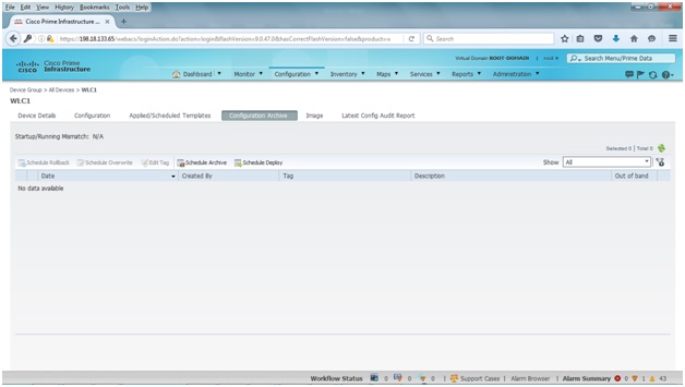
You'll be able to see all the WLC details by clicking on the tabs
such as Device Details, Configuration,
etc.


You can also view the same tabs under Monitor.


You can view various device health graphs and statistics under Dashboard.


You can also monitor and view the details of the associated wireless
clients by going to Monitor > Clients and Users. Click the radio button
beside the MAC address to view the client’s full details.


No comments:
Post a Comment